Photographs have been adapted for the website; dimensions may vary.
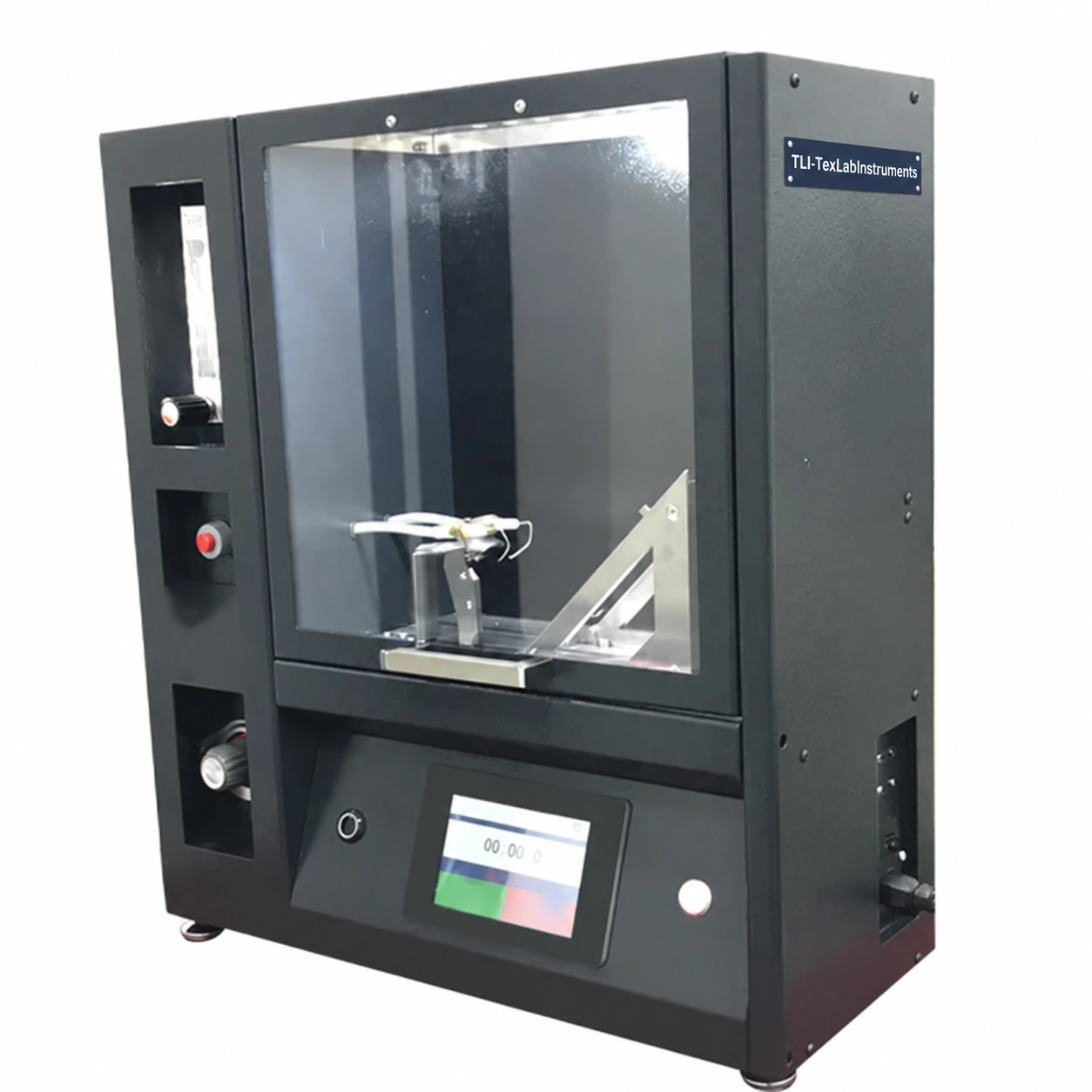
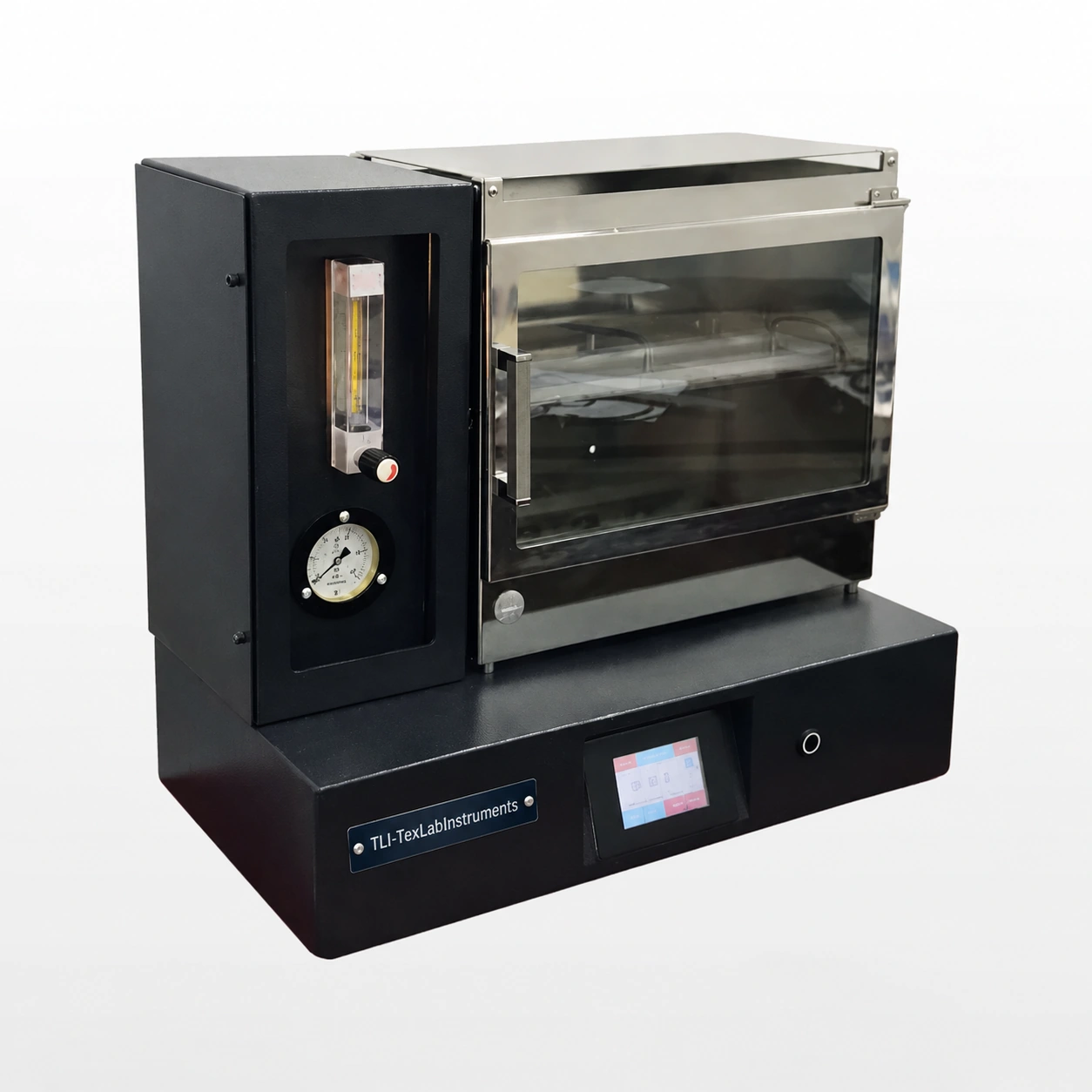
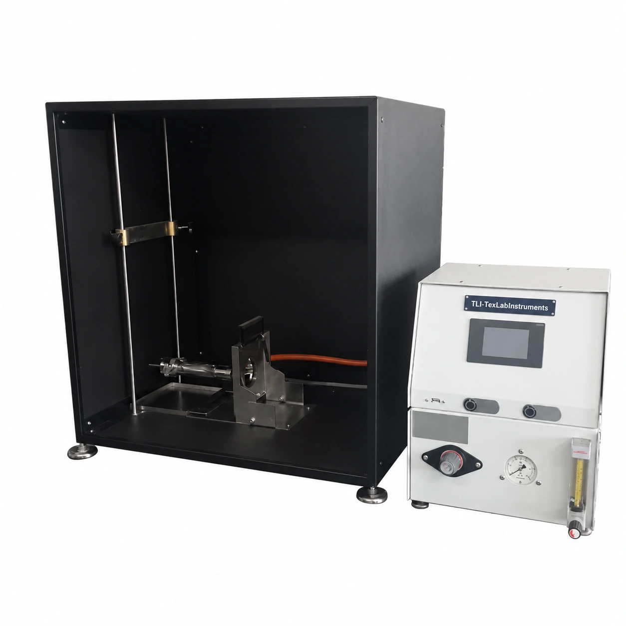
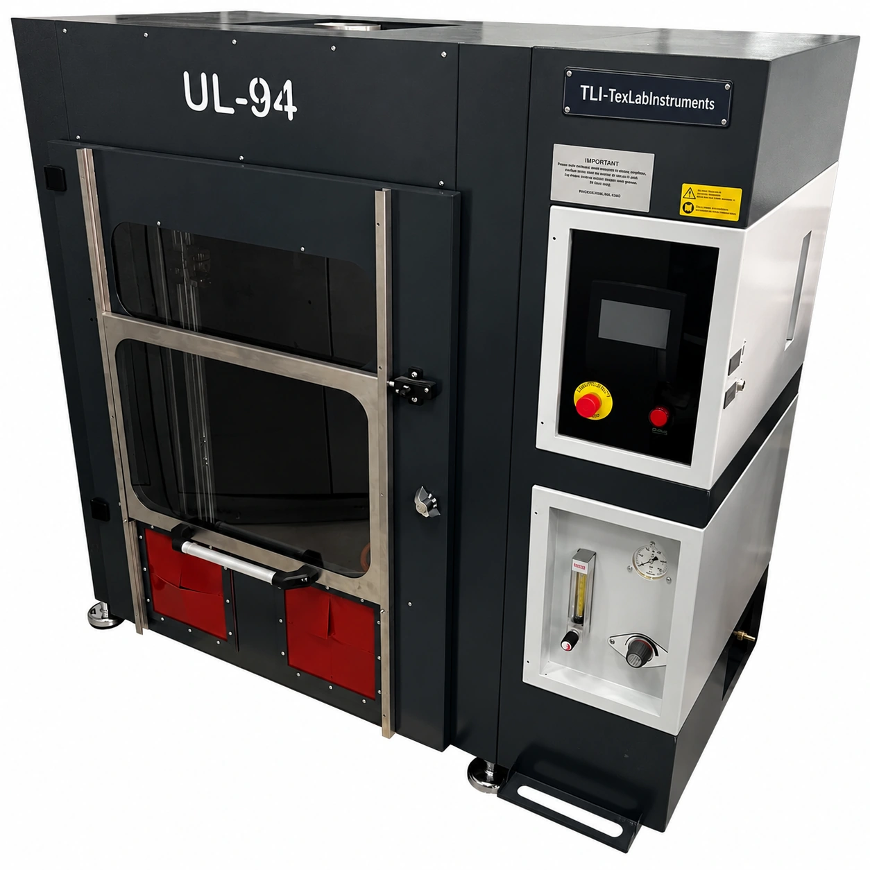
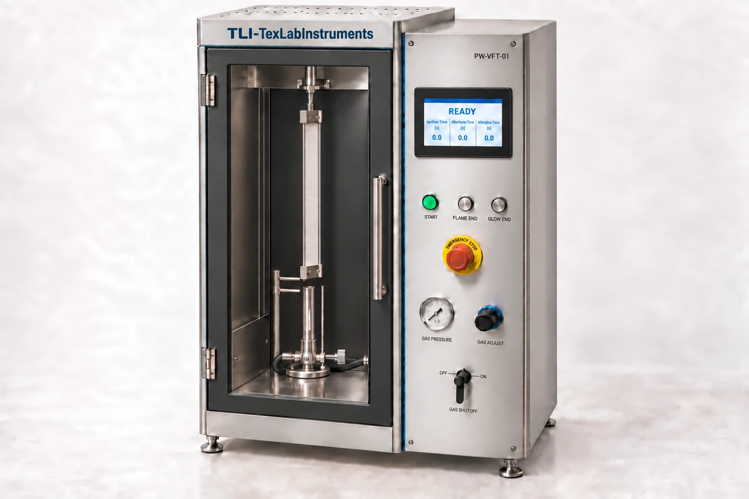
Vertical Flame Spread Tester
Dikey Yanmazlık Test Cihazı
Testing ignition and flame spread of vertically mounted textile specimens. Configure specimen holder and timing channels for the selected test method.
Model technical data
- Different test methods can be loaded via the touch-screen control unit and computer connection.
- With dedicated fixtures, flammability tests on toys, curtains, covers and upholstery are also possible.
Physical specifications and utilities
| Electrical supply | Manufacturer PW-VFT-01 brochure: 230 V AC, 50/60 Hz. Confirm phase, total connected load and protection rating against the order wiring diagram/nameplate. |
|---|---|
| Power / connected load | Approx. 50–200 W connected load for preliminary planning. |
| Overall instrument dimensions | Approx. 900 × 700 × 1500 mm (W × D × H). |
| Instrument weight | Approx. 50–100 kg net. |
| Gross / shipping weight | Approx. 80–150 kg gross; estimated packing allowance. |
| Gas requirements | The ASTM configuration requires a methane source (99% purity) and external hood; avoid drafts at the specimen. Select the gas/burner set for the method; accessories for other methods are not assumed included. |
| Lab requirements | Method-specified test gas, regulator and exhaust / fume hood; gas type and flow follow the selected method and burner. |
Dimension order and approximate values are stated in each row. Packaging data are separate from instrument dimensions and net mass. Approx. rows are preliminary engineering estimates based on comparable equipment and function/capacity; they are not verified manufacturing measurements or standard requirements. Installation and shipment are finalised against the approved drawing and nameplate. Estimate scope: base product / one unit; external computer, bench and auxiliary plant excluded.
Specifications, dimensions, and power requirements are approximate and subject to change without prior notice for continuous design improvements.
Product technical specifications and images may vary according to manufacturing conditions and applicable standards.
Test and configuration
- Measured output / function
- Afterflame, afterglow and damaged length
- Parameters selected for the method
- Vertical holder, method-specific burner and flame application time
- Verification points
- Burner/gas flow, geometry and timing
Listed methods are application references. Suitability is established by assessing the selected hardware, current method and calibration together.
Test parameters for the reviewed method
Values belong to the stated source edition. Test recipe, fixture and delivered instrument configuration are selected together.
TS EN ISO 15025:2006 · 6.5-6.6
- specimen template 200 × 160 mm; flame-application timer adjustable in 1 s steps with accuracy 0.2 s or better. Afterflame and afterglow are measured on separate channels with readability 0.2 s or better.
ASTM D6413-99 · 6.2-6.8, 8.2
- Vertical-flame method: burner bore 10 mm, length 76 ± 6 mm; methane purity 99% and inlet pressure 17.2 ± 1.7 kPa. Flame application 12 ± 0.2 s; burning times measured with 0.2 s readability.
ISO 6941:2003 / TS EN ISO 6941:2007 translation · 5.1, 5.4, 5.6, 8
- Specimen size is 560 by 170 mm with ±2 mm cutting tolerance. Provide separate timing channels for three marker threads, readable to 0.2 seconds or better and stopping automatically when each thread breaks. Record ignition and flame-spread procedures distinctly.
ISO 6940:2004 · 5.1-5.6
- Vertical ease-of-ignition method uses a holder with 190 × 70 mm pin spacing and a 200 × 80 mm specimen template. Flame application adjusts in 1 s steps with error no greater than 0.2 s; afterflame timing 0.2 s or better. Select the propane/butane setup separately from methane ASTM fixtures.
BS 5438:1989 + Amd.6509:1990 + Amd.8308:1994 · 3.1–3.2, 4, 5.1–5.4.2, Figures 1–2; preview ends printed p.4
- 1989 + Amd.1/2 edition: condition at least 24 h at 20 ± 5 °C and 65 ± 5% RH; start each test within 2 min of removal from conditioning or sealed storage. Test at 15–30 °C, 55 ± 20% RH; initial air movement <0.2 m/s. Restore the test atmosphere after smoke extraction.
- Test 2A/2B holder pin rectangle 190 × 150 mm; pins maximum Ø2 mm, minimum length 27 mm. Adjacent spacer stubs Ø2 mm, minimum length 20 mm. These are specimen-holder dimensions, not cabinet exterior size. Burner mounts vertical/horizontal or 30° to vertical; stand-by tip at least 50 mm in front of the specimen.
- Commercial butane to BS 4250; Figure 2 gas-jet orifice Ø0.19 ± 0.02 mm and burner-tube length 40 mm. Select this gas/burner configuration separately; no equivalence to a general Bunsen head is assumed. The 1994 amendment deleted 1A/1B and 3A/3B; verify the remaining setup and procedure for retained 2A/2B separately.
Control and recording specification
The following are method-specific software/recording requirements; delivered software modules are defined by the order scope.
- Method code and edition, specimen ID, operator and selected test parameters are linked to the record.
- The calculation and endpoint are defined by the selected method edition; instrument signals and operator assessments are kept distinct.
- Raw measurements, units, valid/invalid test flags and the reported result remain traceable.
- Calculations are checked against known inputs and an independent calculation; sensor channels are checked against calibration values.
- The BS 5438 recipe records edition/amendment, face/bottom-edge ignition, conditioning/test-start times, flame application, afterflame and afterglow separately. Deleted tests are not selectable as active recipes of this edition; dedicated fixtures and delivered modules depend on order scope.
Historical method references (current method and fixture require separate review): BS 5438
Download the technical brochure (PDF)Revision: 27 October 2026Test standards
Prices start from €18. Request the technical specification and a quotation for this instrument.
Request a quoteCall usPDF catalogue